Tuesday, March 27, 2012

Even the small buildings benefit from BIM

Can you identify the 4 issues in this corner of the 4,500 sq.ft. library at Little Mountain?:

and the answer is...

1.  Exposed fire protection pipe.
2.  Light fixture in the path of the projector image.
3.  Light fixture in sloped soffit.
4.  Wall diffuser in soffit.

Tuesday, January 31, 2012

Why does my model look sectioned?

Does your model section itself when you try to navigate through it? 


One of the most common reasons for this is spurious objects located away from the actual model.  To see if there are objects "floating in space" in your model, do a Zoom All (Page Up) of your screen:


If this is the problem the best way to fix it is to have whomever is responsible for the floating objects to remove them from their model.  If you do not have time and need a quick fix, the "Hide Unselected" tool is perfect for this.
Zoom into your model.
Use the Select Box to window around the model you want to keep.


Click on "Hide Unselected" under the Home tab

Your model should now only display the objects that matter and function better during navigation.

If this does not fix your issue then there is additional information about clip planes on this website: Autodesk Beyond Design Blog

Friday, December 16, 2011

Suffolk-Roel was at the Autodesk University 2011

Suffolk-Roel was amongst the hundereds of companies that attended the AU 2011 conference this year. Annual Autodesk University conference is one of the premier Autodesk learning and networking event for designers, engineers, and industry and technology leaders.Want to know more about the Conference? Here is a review of the event by AECCafe Weekly: http://www10.aeccafe.com/nbc/articles/view_weekly.php?articleid=1038905&page_no=1

Tuesday, December 13, 2011

Footing influence

Quite often the underground utilities are designed to run close to the building.  Structural engineers require utilities to stay out of the area of influence or angle of repose from the structural building footings.  Combining the civil layout for utilities with the structural "no fly zones" in BIM has proved to be extremely helpful in the site utility coordination for the Little Mountain project.


Wednesday, November 9, 2011

Mirror mirror on the wall, where's that catch basin after all?

Suffolk-Roel Superintendent Frank Conte participating in BIM site utility coordination weeks before the shovel hits the ground.

Monday, October 24, 2011

How do you hide the pipe between point A and point B?

Have you ever seen one of these statues where it appears that water is pouring from a faucet without a supply pipe?

Unfortunately on our projects to get water from point A to point B we need a pipe (and a wall to hide it in).  Thanks to BIM we were able to identify an area on our Icon project where plumbing was designed to run down to a sink where there wasn’t a wall to hide it in.  Finding this issue early now gives us the option to look at other walls and ways to get the water supply to the sink without impacting the cost and schedule of the project.

Thursday, October 20, 2011

Blue Book Building and Construction Network

Today Suffolk-Roel represented General Contractors in a BIM panel discussion/presentation for the Blue Book Building and Construction Network.

Thursday, October 13, 2011

24" > 9"

When trying to see if there is sufficient clearance for an exterior exhaust fan louver:   the ceiling elevation can be found on the RCP drawing, the ceiling framing size in the detail sheets, the louver size in the mechanical drawings, the steel elevations in the steel drawings (with a little more math to account for the curve in the steel), and the exterior soffit details and dimensions in the structural and architectural drawings.  If you combine all of these you might discover on the Colton High School project that the 24” louver is greater than the 9” of available space.

An easier way to discover this issue was when the mechanical, structural, and architectural models were combined in BIM:


A quick snapshot of the model and a section view of the issue were created and given to the architect for review.


Finding this issue early helped to avoid any rework and cost/schedule impacts that might have happened had this issue not been noticed until after the steel, block wall, and ceiling framing were installed and louvers purchased/delivered to the jobsite. 

Thursday, October 6, 2011

Misc. metal matters

What happens when theatrical rigging submittals are not received until after MEP coordination?


Clash!! :


Walking the room in the field, taking photos with the iPad, and analyzing alternate coordination options in the BIM model provides us with images and scenarios that we can use to communicate with the applicable trades (and design team if needed) to minimize any impact that this issue might have had on the project.


Tuesday, September 27, 2011

Connections matter

On Middle school #3 the site utilities were modeled for coordination.  In the field there is always a debate about who makes the final connection.  In the BIM world we ran into the same situation...two trades with connecting models but neither taking the time to create the connection.

The focus of our BIM site utility coordination was to check for clashes between systems that crossed each other and not necessarily focused on the connections.  Besides, this connection looks ok in the model, right?


Wrong.  As was discovered in the field and as you can see in an elevation view of the model below, this connection would require the sewer line to run uphill.


The root cause was an error in the Civil drawings that showed the connection elevation lower than the rest of the sewer system:

Once this issue was identified the BIM model was very helpful in looking at and testing other options in a virtual environment; however, had this connection been modeled in the 1st place, the issue would have been discovered before the pipe was in the ground.  Lesson learned.

Wednesday, September 7, 2011

Constructability Review

One of the benefits of BIM is having a 3D overlay of the architectural and structural details for constructability review.

On the Colton High School project during the 1st BIM coordination meeting the architectural model was federated with the steel subcontractors model.  During a virtual walk through it was noticed that all of the windows had steel framing above them with the exception of two on the west side of the building.


Upon reviewing the contract documents it was noticed that these supports were shown on the architectural drawing but not on the structural plan.  As a result the structural steel subcontractor did not notice the ones that are missing during their steel detailing:


These supports are attached to the building with an embed in the exterior block.  If this issue had not been caught until after construction of the exterior wall, it could have been expensive to find an alternate fastening solution, could have caused potential damage to the block wall, windows, landscape/hardscape (depending on what phase of construction this issue would have been discovered), and could have caused an impact to the schedule if these items were not fabricated as part of the original steel package.

Detail showing connection to wall:


Friday, August 12, 2011

Keeping building maintenance in mind

For the COC project we modeled VAV access zones and ladders to simulate access to this equipment by the future facility maintenance crews to help prevent this:

This VAV fit in the ceiling space, does not clash with steel or other MEPs; however, it became obvious that it would be impossible for a maintenance worker to safely reach the VAV because of the hard lid/ACT transition and framing.


This simulation also allowed us to make sure maintenance ladders would not conflict with room furniture or other objects.


With these areas modeled we could also see where access panels would be located in relation to light fixtures.

Wednesday, August 3, 2011

High School #12 Site Utilities

An unforeseen obstruction on site during the installation of the water lines required a deviation from the coordinated model.  Using the model with the subcontractor’s field foreman, Suffolk-Roel Superintendent Steve Foley used the site utility BIM model to confirm dimensions, elevations and explore other options for utilities and fence post supports.


Monday, August 1, 2011

County Operations Center-Conference Center, San Diego Signed Off!


Suffolk-Roel’s BIM team signed-off the BIM Coordination for County Operations Conference Center in San Diego. This 20,000 square-foot conference center is scheduled to be completed in October 2012. The building is designed to comply with a Platinum Certification level according to the U.S. Green Building Council’s Leadership in Energy Efficient Design (LEED) Rating System and has green features like green roof and solar tubes!  The structure will have combination of pre-cast concrete panels, metal panels and aluminum storefront for the skin.

Here are some Build Smart facts for COCCC:

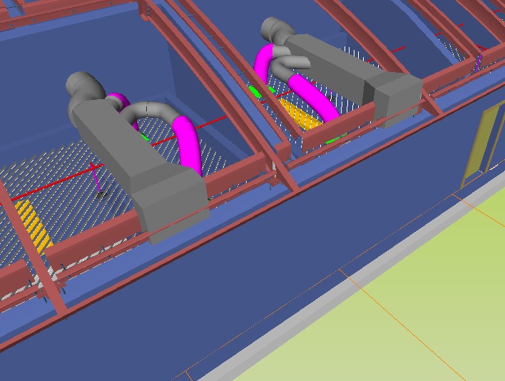
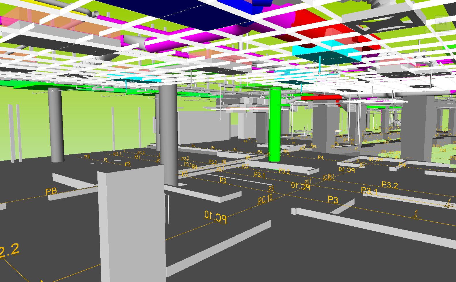
·         The BIM Coordination of mechanical, electrical, plumbing, fire protection and architectural systems allowed the COC project to avoid construction conflicts that typically would have been encountered during actual field installation. We started with over 2000 clashes and signed-off no clash coordination! 
·         Having a coordinated 3D virtual model also allows our subcontractors to prefabricate their systems rather than shipping raw material to the jobsite for construction. Avoiding rework by avoiding conflicts in the field and prefabricating systems will reduce the amount of scrap material and waste on this project. 
·         Coordinating these systems in a 3D virtual environment also allowed easier analysis of MEP equipment placement which translates to easier equipment maintenance and operation during the future lifecycle of this building.
·         7 out of 10 meetings were conducted through web-based GoToMeeting rather than the typical on-site/in person MEP coordination meetings.  We saved an estimated 1421 miles in automobile travel on this project.

Suffolk-Roel’s involvement and innovation in this project shows the West Coast region’s continuing support of the company’s overall dedication to building smart, sustainability and green building practices.


Friday, July 15, 2011

Soldier Beam

On the Icon project the soldier beams extend out into the parking garage.  The question is to leave them in place or cut them flush to the wall.  Adjusting the soldier beams in the BIM model per the field locations gives a quick look at the impact it would have on the MEP systems to help with the design decision.  Quick images like this will also help clarify and expedite the RFI  process.

Soldier beam in water line

Soldier beam in duct

Soldier beam in sewer line

Port Lawrence - 5D BIM

Port Lawrence is a multi-faceted Hotel / Conference Center project in Palm Springs, California.

It has the following elements to it:

1.  Concrete Parking Structure
2.  Concrete Podium, which has retail spaces, event / conference center, restaurant w/ rooftop bar and spa & fitness center
3.  Four story hotel, which switches to a wood framed structure above concrete podium
4.  Lots of site work:  pool, exterior bar that services the pool, landscaping and hardscape


The following images from Keith Kauffman are models created in DProfiler for 5D BIM cost estimating


Thursday, July 14, 2011

Model vs Field comparison

LAUSD Middle School #3 Building D Corridor:


MEP Coordination meeting

MEP coordination using a federated BIM model and GoToMeeting

Friday, July 1, 2011

EcoDomus

Today Daren Roos, Anamika Sharma, Keith Kauffman, Steven Jennemann, and Rob Latch met with Sean Olcott, email: solcott@ecodomus.com from EcoDomus to discuss their 6D BIM facility management solution.

Click on the virtual business card to learn more about Sean:


Click on the image below for more information about EcoDomus:

Tuesday, June 28, 2011

Granite Park animation

This quick animation was created in Sketchup to help explain the sequence and locations of project renovation.

Friday, June 24, 2011

International Revit Technology Conference

Today Suffolk-Roel represented General Contractors in a BIM panel discussion/presentation titled "Collaborative BIM for Construction" at the Revit Technology Conference.


Tuesday, June 14, 2011

CAM 2011

Darren Roos met with Steve Dales from Orange Technology to beta test a new 6D software called CAM 2011.  It is much like Navisworks however it also allows the user to edit and add properties.

Monday, June 13, 2011

Subcontractors can do it too

Salamander Fire Protection's foreman Bill Felder installed Navisworks Freedom on his personal computer so that he could use the BIM model to validate his shop drawings, for pre-task planning, and for reference during installation.  Below is Bill using the measure tool to check his fire main elevations in the model.

Measure tool: